- Mon - Sat: 7:00 - 17:00
- 825 975 3689
- sales@limegreen-worm-616364.hostingersite.com
A secondary suite is a second self-contained dwelling unit that is located within a primary dwelling unit, where both dwelling units are registered under the same land title. A suite may be located in a Single Detached House, a Semi-detached or Duplex House, or a Row House. A secondary suite is commonly below the principal dwelling unit of the House, but may be on the same level as or above it and may have more than one storey.
Each unit in a Semi-detached House or Row House is considered a “House” for this purpose. A House may not contain more than two dwelling units: the main home, referred to in this guide as the principal dwelling, and the secondary suite, as well as any common spaces such as storage, service rooms, laundry or halls and stairs used for access and egress (exit) routes.
If you intend to add a secondary suite in future, be certain to review the Suite Rough-In section.
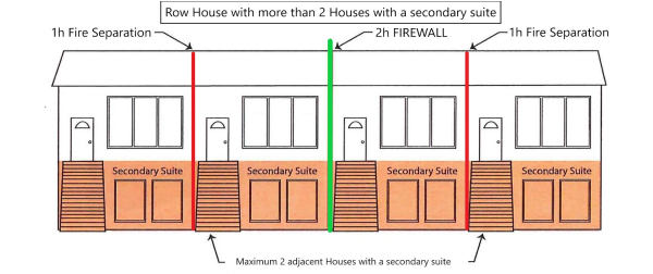
There is a limit of two Row House units with a secondary suite in a Row House unless it is constructed with a firewall such that no more than two secondary suites will exist (in addition to the principal dwelling units) between firewalls, firewall and end wall, or end walls of the structure. This firewall requirement is more stringent than the typical 1h fire-resistance rated separation party wall in a Row House that contains no more than two Houses with a secondary suite in the entire building.
A firewall is a robust type of non-combustible fire separation designed to remain standing if part of the structure on one side of it collapses in a fire. Establishing a firewall after the Row House is constructed is impractical and so an alternative solution would be required to provide an equal or better level of safety and performance to a firewall. See Letter of Acknowledgement re: NBC(AE):B:9.10.11.2. if you wish to proceed with new Row House construction without firewall provisions or construct one or two Houses only with a secondary suite in an existing Row House. Where required firewall(s) design is a gypsum shaftliner “area separation wall” system, review potential solution in Policy 19-03 – Area Separation Walls about systems using non-loadbearing protective walls. Other types of firewalls require engineering review and consideration of parapets, combustible projections, etc., per NBC(AE).
Note: Apartment buildings per NBC(AE):B:9.10.14. have more than two dwelling units and thus may not have secondary suites. Note: Row Houses with 5 or more dwelling units require professional involvement per NBC(AE):C:2.4.2.1.(3), however 2.4.2.1.(1) indicates secondary suites are not to be considered as dwelling units when calculating the total number of dwelling units.
A ‘means of egress’ is the route from anywhere in a building to the exterior ground level and from there to a safe place such as a public roadway.
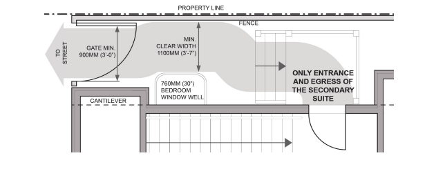
Where a secondary suite cannot be accessed by emergency responders (fire or ambulance) through the principal dwelling main door, ensure an exterior 1100 mm clear width path is available from the street to the suite entrance door. Any gate along this path must be non-locking and capable of opening to 900 mm (see figure below).
A suite exterior exit doorway, passageway and stair (or ramp) exposed to a window or hazard from the common area or other suite in a House with a secondary suite will need to be protectedif there is not an alternate means of egress from the suite. Specifics are discussed here:
If there is not a second ‘means of egress’ other than by an exterior exit stair, then that stair must be protected from all the windows of the other dwelling and common spaces located within 3m (10’) horizontally of the exit stair, below it, or up to 5m above it. This also applies to windows in exterior doors, and also applies to an exterior exit ramp (see figures below; NBC(AE):B:9.9.4.4.)
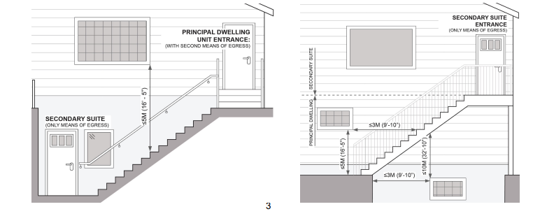
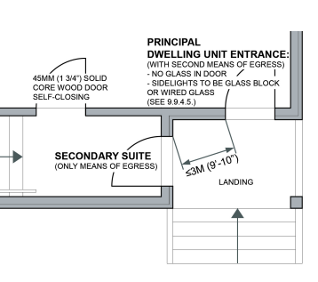
If there is not a second ‘means of egress’ other than by a single exterior exit door, then that door must be protected from all windows of the other dwelling and common spaces located within 3m (10’) horizontally of the exit door(s) in facing walls or walls built at angles < 1350. This also applies to windows in exterior doors (see figure on the right; NBC(AE):B:9.9.4.6.)
If there is not a second ‘means of egress’ other than by an exterior deck or veranda platform passageway that is located more than 1.5m (5’) above the finished ground level, where one dwelling is located above the other dwelling or common spaces, then that passageway must be protected from windows of the other dwelling and common spaces below it by building the passageway with minimum ¾h fire-resistance rated floor assembly or provide more than one exit stair (or ramp), i.e., provide two ways off the passageway, in opposite directions, so there is an alternate route to safely get down to ground level. (see NBC(AE):B:9.9.9.3.)
Protection of window openings may be with wired glass (per NBC(AE):B:9.10.13.5.), or glass block (per NBC(AE):B:9.10.13.7). 20-minute fire-protection rated labeled closures–rated windows, doors or shutters tested in accordance with NBC(AE):B:9.10.3.1. and installed and maintained per NFPA-80 and the manufacturer installation instructions–are also acceptable. Establishing a desirable protective measure after the House is constructed is sometimes impractical and so an alternative solution would be required to provide an equal or better level of safety and performance to the window openings protection; for example, sprinkler-protection may be considered.
The access and exit from each dwelling may not be through the other dwelling or through a service room. All rooms that make up a secondary suite are to be contained within the suite, and not accessed by moving through common areas or the principal dwelling. Ensure that
● any hall, corridor or passageway within a suite or in the common space is to be unobstructed
clear width ≥ 860mm (34”),
● unobstructed clear height of the walking surface leading to the exterior, including over the
stairs, ≥ 1.95m except that the clear height may be ≥ 1.85m under beams/ducts; an obstruction
is anything projecting into required minimum provisions (width X height),
● any doorway providing access to exit and exit from a secondary suite is
○ ≥ 1980mm (78”) high,
○ ≥ 810mm (32”) wide, and
○ may swing inward.
Every room intended for sleeping in an unsprinklered building requires emergency egress: a door to the exterior OR egress window, as shown here, with the following characteristics:
● openable from the inside without removing sashes or any hardware and without keys, tools or special knowledge,
● any security bars and exterior protective cover must open from inside without keys, tools or special knowledge,
● the window has to remain open on its own and have an unobstructed area ≥0.35m2 (3.77ft 2 or 543 in 2 ) with any/all dimensions ≥ 380mm (15”), and
● any window well must extend ≥ 760mm (30”) ahead of the window or outward-swinging sash.
Two or more areas are considered a combination room if the opening between the areas occupies the larger of 3m2 or ≥ 40% of the area of the wall measured on the side of the dependent area. Where the dependent area is a bedroom, provide direct passage between the two areas.
Stair or ramp width is to be ≥ 860mm (34”), measured from wall to wall with any projections into the 860mm width not exceeding 100mm (4”) in total.If there is 30” clear between typical obstructions such as a handrail and a wall opposite the handrail, the stair is usually acceptable.
Stair rise, the vertical nosing-to-nosing dimension, in all cases must be in the range of 125-200mm (5”-7⅞”).
Stair run, the horizontal nosing-to-nosing dimension, for rectangular treads must be in the range 255-355mm (10”-14”),
Height over stairs, ramps or landings is
● measured vertically from a line drawn tangent to the tread/landing nosings to the lowest point overhead, and
● clear height must be ≥ 1950mm (76¾”), except it may be ≥1850mm (72¾”) under beams and ducts in a secondary suite.
Spiral Stairs are permitted to be used as the means of egress from a floor area serving no more than 3 persons (see NBC(AE):B:9.8.4.7.).
A landing as wide as the flight that leads to it is required, so ≥ 860mm (34”) minimum follows on stair width. Where another flight leads to the same landing, that would also result in a dimension ≥ 860mm. Hence, the minimum landing dimension inside a House with the secondary suite is 860mm each way. An exterior landing is required to be slightly larger at minimum 900mm long, and at least as wide as the stair which is ≥ 860mm.
Guards must be installed● inside and outside where a difference >600mm (24”) in elevation between a walking surface and a lower adjacent surface exists, where the walking surface is not against a non-climbable wall that is at least as high as the required guard,
● at sides of flights of steps >2 risers (or 400mm ramp rise) where there is no wall,
● at windows in flights of stairs or at landings <900mm (36”) above the walking surface OR the window must be with non-openable, strengthened guard glass (labeled), or
● outside,where the ground slopes away at ≥1:2 (~300) within 1.2m (48”) of the step or ramp served by the guard.
Height of guards for flights of steps or for landings is
● measured vertically from a line drawn through the leading edge of treads to top of guard,
● ≥900mm (36”) from walking surface to top of the guard for any location inside the House with a secondary suite,
● ≥1070mm (42”) from the walking surface outside the House, except ≥900 (36”) where the difference between the walking surface and a lower adjacent surface is ≤1800mm (71”).
Openings in guards are to prevent
● passage of a 100mm diameter sphere where a guard is required, and
● where a guard is not required, passage of a 100mm diameter sphere OR have openings that will permit the passage of a 200mm spherical object to reduce risk of entrapment in the guard.
Design of guards must be engineered unless the construction provides demonstrated effective performance, as most commonly-accepted wood guards of workmanlike construction do. Any aluminum, steel, vinyl, composite, and/or glass guard/handrail system must have CCMC evaluation approval, documentation, or engineering indicating compliance with current NBC(AE). No member, attachment or opening between 140mm and 900mm above the walking surface being guarded may facilitate climbing on a guard protecting a level more than 4.2m (13’9”) above the adjacent level.
Handrails must be
● graspable and with no obstruction on or above them to break a handhold,
● with ≥50mm (2”) clearance to the guard or wall (≥60mm if the surface is rough/abrasive),
● continuous from floor level to any intermediate landings, and through any stair winder, and
● connected to wall/support ≤300mm (12”) from ends and ≤1.2m (4’) between OR engineered.
Height of handrails for flights of steps is
● measured vertically from a line drawn through the leading edge of treads to top of handrail,
● 865mm (34”) to 1070mm (42”) except 865mm to 965mm for a ramp. Extra handrails, e.g., for
children, may be outside this range.
No handrail is required where a flight of steps is 1, 2 or 3 risers from landing to landing, landing to floor, or on a ramp with a rise ≤400mm (16”).6
A separate, independently-controlled heating/ventilation system must serve the secondary suite, and may not be interconnected/ducted with the remainder of the house. A heat source alone, without ventilation, is not sufficient. The typical solutions are:
● a separate forced-air furnace for the suite, with independent, dedicated ductwork,
● hydronic radiant heating and independent ventilation such as heat recovery ventilator (HRV), or
● electric baseboard heating with independent ventilation such as an HRV.
Ventilation air is filtered, heated fresh air to provide acceptable indoor air quality. Ventilation air is not required in common spaces. Ventilation is often provided through an insulated fresh air duct from outside to the return air duct of the forced-air furnace system where it is warmed and then distributed throughout the space served by the forced air furnace. A primary ventilation fan must be installed; this exhaust fan must be interlocked with the forced-air furnace to introduce a balanced amount of ventilation air into the suite through the fresh air duct. Kitchen and bathroom exhaust fans must be installed to remove smoke, steam, heat and odours.
A Heat Recovery Ventilator (HRV) or Energy Recovery Ventilation (ERV) is another common solution to satisfy the need for ventilation supply and exhausting air.
Make-up air is replacement air to prevent excessive depressurization, required to compensate for the operation of appliances and exhaust equipment such as kitchen and bath fans, fireplace, clothes dryer, built in vac, etc. An air exhaust system or a non-direct-vent fuel-burning appliance removes air from a house, creating a slight negative pressure inside. In certain cases the natural flow of air up a chimney can be reversed, leading to risk of carbon monoxide poisoning. Depressurization can also contribute to increased entry of soil gas (radon) through basement floor and wall cracks.
Newer or renovated houses are generally more tightly constructed than older ones, with less-draughty windows, newer weather stripping and caulking. This increases the probability that infiltration of air from joints and penetrations in the exterior walls of the house may not be able to supply enough air to compensate for simultaneous operation of exhaust fans, fireplaces, clothes dryers, furnaces and space heaters, so it’s necessary to introduce preheated outdoor make-up air to the space.
Combustion air proportionate to combined btu/h input of all non-direct-vent fuel-burning appliances must be provided to the rooms containing the appliance(s).
Additionally, check that these miscellaneous conditions are satisfied in the House:
● no return air grilles or return air duct openings inside a furnace room,
● gas dryer vent pipe is galvanized, otherwise galvanized or aluminum; not corrugated flex duct,
● covers installed on hydronic or electric baseboard radiant heating,
● yellow-jacket CSST flex gas line is not permitted to connect directly to an appliance; a labelled factory-made flex gas connector is permitted from appliance to connection point behind it, and
● observe cooktop clearance to cabinets or hood fan listed here, with any over-the-range microwave/fan unit installed according to the manufacturer’s directions.
A completed “Electrical Inspection Load Calculation” form must be submitted with this application before an electrical permit can be issued. From 01FEB2022, the panel for each dwelling must be located in that dwelling or in an adjacent common space accessible by the tenant without going outside or relying on another person to give access to the panel.
Smoke alarm must be hardwired and located in:
● every bedroom AND in the hallway / between the bedrooms and the general floor area,
● common spaces including interior shared means of egress, and
● all ancillary spaces such as storage rooms, washroom, laundry room, or service/furnace/ mechanical rooms that are accessed from the common area (those not within the principal dwelling or the secondary suite).
Smoke alarms must be interconnected so when one sounds then all of them sound. Alarms that use a wireless interconnection system are acceptable, provided they conform with CAN/ULC-S531, “Smoke-Alarms” and are installed per manufacturer direction.
Carbon monoxide alarms must be located in a House that has an attached garage or any fuel-burning appliances (gas furnace, solid-fuel-burning fireplace, etc.) in:
● every bedroom OR in the hallway/within 5m of bedroom doors,
● service/furnace/mechanical rooms with gas-fired appliances not within the suite, and
● any room with a wood-burning fireplace, wood stove or other solid-fuel-burning appliance. Carbon monoxide alarms in a House with a secondary suite must be interconnected so when one sounds then all of them sound. Alarms that use a wireless interconnection system are acceptable, provided they conform with CAN/CSA-6.19,“Residential Carbon Monoxide Alarming Devices” and are installed per manufacturer direction.
Sound Separation
Sound absorbing material (eg., batt insulation or cellulose fill) must be installed in walls and floor-ceiling assemblies between the secondary suite and the principal dwelling, as well as between the suite and non-suite space where noise may be generated (e.g., shared laundry, furnace room). Sound protection requirement is satisfied where
● ceiling cavities are filled with ≥150mm (6”) thick batts or cellulose sound-absorbing material,
● wall cavities are filled (not overfilled) with batts or cellulose sound-absorbing material, and
● resilient channels (‘sound bar’) are installed on one side of the walls and on the underside of the floor-ceiling assemblies.
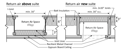
Return air runs through floor joist or wall stud cavities may not be blocked with, communicate with, or be exposed directly to fibre materials that may get into the airstream and circulate through occupied space. Use a joist liner to separate non-ducted return air space where resilient channel (sound-bar) and/or insulation is present. Where return air is non-ducted in a House with a secondary suite, it is acceptable to reduce the batt insulation to ≥75mm (3”) but isolate it from the airstream with joist liner, gypsum, etc. The HVAC installer needs to ensure that the remaining space is sized to allow sufficient air flow back to the furnace. In older homes with 2×8 floor joists or in large homes there may be a need to use two joist spaces for the return air to each furnace. An acceptable arrangement related to a secondary suite follows:
Alternatively, select and construct an assembly
● with an STC rating ≥43, per the NBC(AE) ‘Assembly and Sound Tables 9.10.3.1.-A / 9.10.3.1.B.’, or
● with adjoining constructions which together provide an ASTC rating ≥40.
Or, finally, if the assemblies already exist (e.g., ceiling in) or cannot be found in NBC(AE), provide an acoustical-engineer-stamped report prior to final inspection demonstrating ASTC ≥40 ASTC is achieved.
Confirm which compliance path is being followed on the Sound Separation Declaration form and provide it with the building permit application.
A continuous smoke-tight barrier of a minimum 12.7mm (½”) thick standard gypsum board is required on the underside of floor-ceiling assemblies and on both sides of wall framing to separate:
● the principal dwelling and the secondary suite from each other,
● common spaces including interior shared means of egress from the rest of the house,
● storage, laundry, and other common-area ancillary rooms from the rest of the house, and
● all rooms containing any fuel-fired space-heating or cooling appliance, fuel-fired service water heater or gas laundry dryer from the rest of the house.
Doors in smoke-tight barriers must be minimum 45mm solid-core wood, with self-closer.
Changes to beams/columns/bearing walls/floor frame To accommodate suite construction, a bearing wall may need to be removed and replaced with a beam, or perhaps a column location under an existing beam needs to be adjusted. Structural changes to your House may be made as part of the suite project, with good information provided.
Window openings, for egress or general improvement
Engineer-stamped design is required for changes to a foundation wall where any of the following conditions is present:
● the existing typical cast concrete foundation wall is degraded due to poor original quality/placement, age/soil conditions, adjacent driveway stresses or poorly drained soils subject to freeze-thaw cycling, and so on,
● enlarging an existing opening or making a new opening in a typical cast concrete foundation wall will result in a window opening more than 1.2m wide, 9 Source: National Building Code-2019 Alberta Edition and NRC. Every project is unique. Commentary and clarification is for information only and may not apply to conditions or circumstances specific to a particular project. Refer to NBC-2019AE for exact wording and final determination of compliance. 4 NOVEMBER 2022
● enlarging an existing opening or making a new opening in a typical cast concrete foundation wall where a point load (from any beam or wall opening exceeding 3m in length) is above or within 300mm (12″) of the proposed opening,
● the length of foundation wall remaining between any two window openings is less than the average of the widths of the two window openings,
● the sum of the widths of all openings on one foundation wall face after alteration will exceed 25% of that wall length, measured from interior side,
● a window opening is to be cut or enlarged in any PWF, ICF, precast, block or brick wall; OR
● a new basement-level entrance is proposed; engineer design is also required for the retaining wall and new and existing footing frost protection. Show plans for the steps up to grade, weeping tile provisions, and lower landing drains if not a covered entrance. List any plans for work on these that may need attention before a suite can be established:
● Foundation repair
● Weeping tile installation or replacement
● Sump pit installation (any sump lid must be securely fastened down with a gasket seal)
● Backwater valve installation (requires a plumbing permit).
Waterproof finish(es) shall be provided to a height of
● ≥1800mm (72”) above the floor in a shower stall,
● ≥1200m (48”) above the rim of a bathtub equipped with a shower, and
● ≥400mm (16”) above the rim of a bathtub not equipped with a shower. Joints between wall tiles and a bathtub are to be suitably caulked with mildew-resistant sealant. Glass other than safety glass shall not be used for a shower or bathtub enclosure.
Consult Soil Gas Vent Termination guidance to complete a soil gas/radon rough-in system, if desired, if testing has demonstrated actionable levels in the house. AHS regulations indicate requirements to address actionable levels of soil gas/radon detected in rental premises. See various established resources, like The Lung Association or EvictRadon for more information.
Operable windows require insect screens installed when open. Wall vent hoods and other exterior building envelope penetrations should be properly flashed and sealed so precipitation, insects and vermin cannot enter. Review the Homeowner’s Guide to Flood Prevention for good property drainage tips.
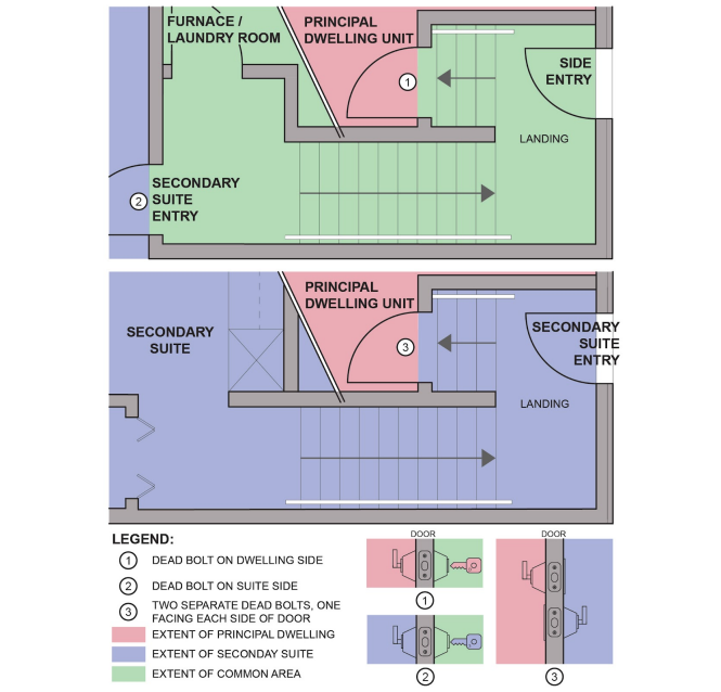
Every entry door into a dwelling–principal dwelling or secondary suite–must be provided with a means of resistance to forced entry–typically a deadbolt lock (NBC(AE):B:9.7.5.2.). This applies to interior suite doors from the common area, and also applies to any door located directly between the principal dwelling and the secondary suite where there is no common area, which must have two separate deadbolts operable from opposite sides not using a common key, so that mutual agreement is required for the door between the two to be unsecured.
For example, if a suite entrance is locked off from the principal dwelling at an interior door such as at a back/side entry, so that the basement stair and entire basement is part of a basement secondary suite, then the 1¾” solid-core demising door at the top of the basement stair must have separate deadbolts operable from opposite sides not using a common key. (This is depicted in figures below.)
The Landlord and Tenant Act and Public Health Act Housing Regulation governing rental accommodation, and the Alberta Housing Regulation and Minimum Housing and Health Standards help create conditions that enable a safe and harmonious relationship between all occupants of a House with a secondary suite.
“Notice of Entry” obligations of the Landlord and Tenant Act should come to mind when deciding the location of a water shut-off, furnace room and other facilities that may end up within the secondary suite. The building code does not dictate access; however, depending on circumstances, it may later prove a good idea to include some utility control /device relocation in the permit.
NBC(AE):B:9.36 Energy Efficiency applies to any house built with permits issued after 31 October 2016 and any further construction such as a secondary suite. Equipment is to conform toTable 9.36.3.10 and Table 9.36.4.2. Where the original house efficiency is determined by the performance path energy model, the provided mechanical system efficiencies are typically of higher efficiency than the minimum prescriptive efficiencies, and may not be reduced in the construction of the secondary suite without re-model of the House.
NBC(AE):B:9.36 does not apply to a house built with permits issued prior to 01 November 2016. Follow Standata guidance for component and system efficiencies. Generally, 9.25 thermal
insulation, air barrier and vapour barrier requirements are the minimum permissible, though any lawfully-existing construction predating the minimum values may remain.
Additional information is under the heading National Building Code – Alberta Edition 9.36 (NBC(AE) 9.36). For background and resources, see the National Research Council Canada, or established trade and industry sources such as “BILD Alberta Codes” (see edmonton.ca/energycodes).
Anyone proposing to alter a building shall provide plans and specifications describing any necessary asbestos management and abatement work to Alberta Occupational Health & Safety (OHS). Be prepared to provide confirmation to your trades and the permit office if asked whether asbestos-containing materials with the potential to release fibres have been dealt with per Alberta
Occupational Health and Safety regulations (see NBC(AE):C:2.2.13.1.(6)).
OHS administers oversight of asbestos remediation if needed; guidance is provided here. The permit office does not issue permits for abatement work alone. Review the Alberta Asbestos Abatement Manual to learn about asbestos work in a homeowner-occupied house.
We recommend you review Fire Code-mandated Fire Safety Planning For Construction, Renovation and Demolition Sites, specifically for small buildings. It is the building permit holder’s and owner’s obligation to ensure measures are in place for the protection of persons on or about the work site.
New Home Buyer Protection Act does not apply to alterations to an existing House for a secondary suite that do not result in substantial above-basement level increase in floor area. You can get more information here if the secondary suite is part of a new addition project.
All permits require inspection. A secondary suite may be constructed as part of a new house, or as home improvement project to an existing house.
In a New House project, the secondary suite is included within the scope of the project and work is expected to proceed on the suite space at about the same rate as the rest. As inspections generally follow project progress, extra inspections for the suite-related parts may be needed if work lags. This applies to trades work as well as building permit-related progress.
In a Home Improvement Project involving construction of the secondary suite, an interim ‘ready-to-cover’ building inspection is required in addition to and only after respective trade rough-in inspections. This specific building inspection is intended to review work performed that is to be covered up by gypsum board and other concealing materials. The inspector should be able to see many of the elements discussed in this guide: access and egress provisions; sleeping room egress window; stairs and landings; smoke alarm and carbon monoxide alarm locations (not yet installed); any structural work (e.g., window openings, column or bearing wall modification, etc.); and sound protection provisions, including the resilient channel called when using the common prescriptive compliance path.
Work for a Suite Rough-In, where some work toward a future suite project is undertaken and documented, also requires inspection for a record of acceptable work at time of construction. Inspections will progress to the stage of work listed on the Suite Rough-In Checklist.
Sometimes a plan changes as work progresses. Some minor changes to plans and specifications for an issued Building Permit may be made after construction begins without engaging in the Permit Revision process. Review the Part 9 Project Product Swap and Plan Revision Procedure for details. Other changes are managed through the online Permit Revision process. Ensure the requirements are met before requesting inspection, to avoid an infraction for not building according to plan.
Remember the general rule that work intended to be covered must first be inspected. Standard inspections can be requested under the ‘INSPECTIONS’ heading on the project dashboard at SelfServe.edmonton.ca, or by calling 311 (outside Edmonton, call 780-442-5311). A set number of inspections is included in any permit, and extra inspection fees will be incurred if the limit is exceeded. Extra inspection can be requested by contacting the respective advisors:
HVAC tech desk for concealed duct inspection or similar: by email or dial 780 496 3118
Plumbing & Gas desk for additional rough-in inspections or similar: by email or dial 780 496 3117
Electrical tech desk for additional rough-in inspections or similar: by email or dial 780 496 6674
PLANNING Suite rough-in plans are to be submitted at time of application for permits for construction, clearly outlining the extent of work to be done with the current project, and must be recorded on this form as well. This record is subject to review and potential amendment at the time of the future mandatory Development Permit and Building Permit application to complete the suite, in the context of any changes that may have occurred to the plan, property, codes or bylaws. Code references are to Div B of the National Building Code – 2019 Alberta Edition (NBC2019(AE):B).
CONSTRUCTION per NBC2019(AE) of the proposed suite rough-in construction. Steps to be taken in conjunction with the current project, for both suite and common space:
PARTITION FRAMING in wood [9.23.1.] or metal [9.24.1.] per suite rough-in plan submitted with building permit application.
SUITE SPACE includes future suite and its wall/floor/ceilingboundaries
OR
COMMON SPACE not contained within the suite space nor the principal dwelling
OR
1 Drains and venting is done as follows:
2 Water supply is done as follows:
3 Plumbing fixture connection:
4 Clothes Washer to serve the suite space is addressed by A or B as indicated:
5 Gas supply to serve the suite space is addressed by A or B as indicated:
6 Flue gas venting to serve the suite space is addressed by A or B as indicated:
7 Gas-fired appliance connection
ELECTRICAL SYSTEM listed in 1 and 2 – Effective February 1, 2022, electrical permits will require the panel for each dwelling be located in that dwelling, or in adjacent common space accessible by the tenant without requiring the tenant to go outside or rely on another person for access to the panel.
1 Panel and service to serve the project is done as follows:
2 Branch circuits to serve the suite space are done as follows